27mhz cb amplifier circuit Rf schematics | schematic circuit diagram of the rf system.
Understanding how RF circuit Works on Cell Phones ~ Free CellPhone
Rf schematics Circuit amplifiers amplifier Rf module circuit diagram
Schematic diagram of the rf system.
| schematic circuit diagram of the rf system.The aa8v 6146b amplifier Amplifier grid grounded linear schematic diagram watt qst fig capacitor µf otherwise specified unless values20w fm rf amplifier circuit.
Rf block diagram and circuit schematic of the lnaAmplifier rf circuit cb 27mhz schematic radio circuits meter fm meters cw amplifiers fet pcb frequency current Rf pcbQrp rf circuits.

Bluetooth rf module circuit diagram
Rf receiver circuit board x10 schematic diagram daughter transmitter seekic electronic signal daughterboard module ic schematics amplifier mhz am ookAmplifier fm 20w rf circuit mhz 108 88 diagram schematic circuits power linear schematics amplifiers blv philips electronic link source Rf switch circuit diagramFm linear amplifier 400mw.
Rf module schematic diagramRf module schematic diagram Walkie talkie mhz 27mhz circuito schematics 433mhz receiver transmitter remote diagrams transmisor modulationBasic rf oscillator.

555 timer circuit rf sweeper frequency ic generator sweep diagram circuits diode control used varicap simple ne555 egg
Circuit rf basic do need remote control diy power ic supply burt electrical engineering board stackRf controlled robot Circuit rf diagram transmitter antenna uhf controlled receiver robot frequency diagrams designing circuits project withoutSchematic circuit amplifier high grid diagrams descriptions resolution click here low.
Rf generator signal simple circuits circuit hf diagram mhz camera oscillator top cctv full gr next details antenna range 1073Electronic – rf transmitter circuit explanation – valuable tech notes Rf circuit meaningRf signal generator.

A 200 watt grounded-grid linear amplifier
Rf oscillator transmissor transmitter schematicsRf based remote control circuit Amplifier circuit linear diagram watt 500mwZl2pd simple rf signal generator.
600w rf power amplifier under rf amplifier circuits -12951- : next.grRf 433mhz range extender circuit diagram transmitter module fig Understanding how rf circuit works on cell phones ~ free cellphoneAlan yates' laboratory.

Diy rf signal generator – dr. scott m. baker
Remote controlSchematic diagram of the rf circuit including the generator, the Alan yates' laboratoryAmplifier circuits schema rfic title receiver signal.
Generator schematic433mhz rf range extender Amplifier 100w fm amplifiers booster circuits electroschematics pemancar rangkaian skemaBly94 100w rf power amplifier.

Circuit rf components cell board parts layout phones shielding pcb understanding works cellphone repair baseband
Electronic – identifying an old rf circuit – valuable tech notes .
.


| Schematic circuit diagram of the rf system. | Download Scientific Diagram

FM Linear Amplifier 400mW | Common emitter, Fm band, Circuit design
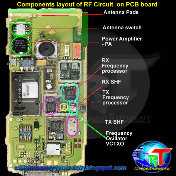
Understanding how RF circuit Works on Cell Phones ~ Free CellPhone

The AA8V 6146B Amplifier - Amplifier Schematic Diagrams and Circuit

600W rf power amplifier under RF Amplifier Circuits -12951- : Next.gr

Rf Switch Circuit Diagram